|
|
Thomas
Penrose's Bamboo Fly Rod Pages |
PART
2: Making Split Cane Fly Rod Planing Forms |
Using
Lawrence Waldron's Alternative Design |
|
|
Thomas
Penrose's Bamboo Fly Rod Pages |
PART
2: Making Split Cane Fly Rod Planing Forms |
Using
Lawrence Waldron's Alternative Design |
I recently had the good fortune to have Lawrence Waldron share with me his design for planing forms. Waldron is a machinist and cane rod builder who has made numerous planing forms, including sets for notable bamboo fly rod builders such as Tom Moran. He also produces fly tying vises. Waldron makes no absolute claim that his form design is better than the push/pull style that most of us have become familiar with, but as a machinist the design of his planing forms are based upon years of professional experience and a well conceived rationale. Consequently, I am sharing this information (with Waldron's permission) so that you may make up your own mind regarding which style of forms you prefer to build. I have not yet built a set of forms to Lawrence's specifications, so this page will be illustrated with diagrams rather than photos. I will also be presenting much of the information that Waldron shared with me by comparing it to the instructions given for making forms on my own webpage. Hence, the information given here will be more easily comprehensible if you already have a working knowledge of the instructions given at my planing forms page, which is linked above.
First, some differences in the materials and their layout:
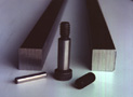
Waldron uses 7/8" x 7/8" steel stock. He uses the larger size because it enables one to make forms that are capable of handling salmon rod tapers, or practically any other large size rod you might care to build. Also, rather than using cold-rolled steel, Waldron uses a steel referred to as EN1A. This is a free machining steel that has a lead content, which has been added to make the steel less ductile and more easily workable. It is therefore easier to drill, tap, file, and cut than standard cold-rolled steel key-stock.
The hardware than Waldron uses, as well as its layout, are also different. As is indicated in the diagram below, he uses 5/16" x 1 3/4" cap-head allen adjusted bolts as the "pull" adjusters rather than using shoulder bolts. The alignment of the forms is held in position by 5/16" x 2" steel dowel pins (these dowels must be ground, hardened ones). For the "push" adjusters Waldron advises using 5/16" x 1" set screws. Notice in the diagram that he has countersunk the area where the set screws push against the the opposite side of the forms. The ends of the set screws tend to create gouged furrows into the forms when they are tightened, and these countersinks keep the resultant burrs from prohibiting the full closure of the forms.
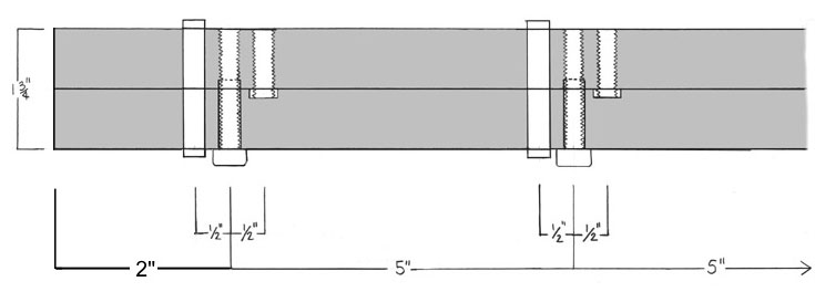 |
| The steel dowels in this diagram are 5/16"diameter x 2" length. The bolts are 5/16"-18 x 1 3/4" length. The set screws are 5/16"-18 x 1" length. All of this hardware is available from Enco if you cannot find it locally. |
Changes in construction procedure:
Waldron normally does not do any extensive draw-filing until the holes have been drilled and the forms themselves have been bolted together. Instead, he lightly dresses the bars with a file in order to remove any burrs or bruises. However, as a machinist Waldron has access to a milling machine in order to cut the tapered grooves into his forms, and since you will probably be using the filing tool method shown on my webpage (or some other method that is done by hand) I believe it is therefore still necessary that the surface of each bar that will ultimately face the other in the completed forms be draw-filed as the first step in the construction procedure. Since you will be using a dial caliper to take measurements from these surfaces when setting the width between the forms when cutting the tapered groove with the filing tool, it is important that they be as smooth and as truly flat as possible.
Drilling the holes:
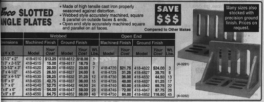
For the drilling Waldron believes that the average person should forego any attempt at using a doweling jig and only use a well adjusted and aligned drill press. He does not use a drill press vise himself, but instead uses an angle plate with a 90° angle (see Enco catalog description below). This plate is bolted or otherwise clamped to the drill press table, and the two bars are clamped into position. using a single c-clamp. Whether you use a drill press vise or an angle plate, it is important that they are properly adjusted (by using shims if necessary) so that the drill will travel through the steel bars at a perfect right angle, rather than at a skewed angle.
|
|
Enco angle plates: The 4 1/2" x 3 1/2" x 3"(#418-4720) would probably be a good size to use. Enco Manufacturing Company: 5000 W. Bloomingdale, Chicago, IL 60639 1-(800)-860-3400 |
The first hole that is drilled will be for a 5/16" steel dowel. Since the dowels are what hold the forms in alignment, Waldron believes that it is important to drill the initial hole approximately 1/64" undersized, and then use a precision reamer in order to create a hole that fits the dowel to as close a tolerance as possible. The dowel should not be difficult to insert, but should fit very precisely. He advises drilling test holes into a piece of steel scrap in order to ensure that the reamer bit chosen for the job results in a hole that ideally matches the dowel diameter. Reamer bits for this job are sold in the Enco catalog. Waldron advises starting the drilling in the center of the forms, and finishing each dowel station and inserting a dowel prior to moving to the next station to be drilled.
To drill the holes for the 5/16" bolts, start by drilling a 5/16" countersunk hole 15/16"-1" into the bars. Without removing the bars from their clamped position on the drill press table, change to a 1/4" drill bit and drill into this countersunk hole until you have gone all the way through the forms.
Finally, you will need to drill the holes for the set screws. To do this you will only need to drill though the single steel bar that the set screws will be mounted in. After drilling these holes, place the form halves together and insert a scribe into each set screw hole in order to mark its position on the opposite bar so that you will know where to drill the countersunk holes that will serve as the contact point for the end of the set screws (refer to the layout diagram above). These countersunk holes will be 1/8" deep and will be drilled with a 3/8" bit. The diameter of the bit is 1/16" larger than the diameter of the set screws themselves in order to avoid any alignment problems.
Tapping the holes:
Since the forms halves are aready dissasembled, start by tapping the threads for the set screws.
To tap the threads for the bolts, assemble the form halves so that you can insert the tapping bit into the 5/16" countersunk holes so that it serves as a guide to hold the bit in alignment as you start to tap threads into the 1/4" holes. If your tapping bit is not long enough to continue all the way, remove it and start the tap on each of the other holes. After you have finished starting each tap you can disassemble the form halves and complete the tapping by working with just one of the bars. Since you started each tap by using the 5/16" countersunk hole as a guide, the tap should already be started out in proper alignment. Using the 5/16" hole as a guide will also reduce the chances that your tap bit will break, since tap bit breakage generally results from side-to-side bending, rather than torque.
When you have completed the tapping you can clean the bars and then assemble them using the dowels, bolts, and set screws.
Draw-filing the forms:
The draw-filing procedure at this stage is the same as described on my webpage. One filing tip that Waldron passed on to me is to occasionally rub the file with a stick of natural chalk, which will reduce its tendency to clog with filings.
Cutting the tapered groove:
Since it is most likely that you do not have access to a milling machine, you will probably be using the same filing procedure for doing this job that is described on my webpage. Likewise, any other procedures for completing the forms from this stage correspond to my webpage.
End
|
|
|
|
|
|
|
|
This fly fishing site created and maintained by Thomas Penrose
All images and text copyrighted ©Thomas Penrose 1997
| The informational content of this bamboo fly rod and fly fishing site is not warrantied in any way or form, and any use of said content are at the reader's own risk, the author shall not be held responsible in any way for any damages or injuries arising from the content of this web site. Common safety practices are encouraged at all times, and the proper and safe use of all power tools and safety equipment (eye goggles, etc.) is the responsibility of the user. |